-
V/F ControlMotor Control/BLDC 모터 제어 2023. 4. 8. 05:22반응형
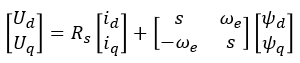
Eq 1 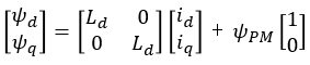
Eq 2. 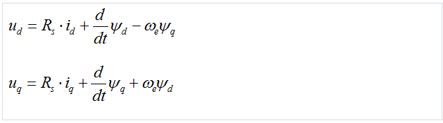
Eq 3. In steady state regime, the flux linkage variation is zero, and for further simplification we are going to assume the stator winding resistance is neglectable.
Taking into consideration these simplifications and the flux linkage equation (eq. 2) then the equations (eq. 3) becomes:
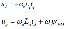
Eq 4. At this point we can transform the electric speed in frequency and rewrite the (eq.4) as a ratio of V/F
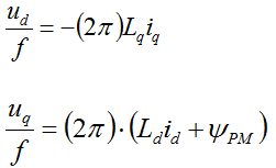
eq 5. In V/F scalar control method the frequency of the stator magnetic flux is set according with the desired synchronous rotor speed while the magnitude of the stator voltage is adjusted to keep the ratio between them constant. No control over voltage or current vectors angles is utilized, hence the name scalar control.
The V/F ratio is calculated from the nominal values of the PMSM voltage and frequency parameters. By maintaining a constant V/F ratio between the amplitude and frequency of 3-phase voltage waveforms, then the stator flux of the PMSM can be maintained relatively constant in steady state. However, in practice a typical V/F profile is not constant over the entire range of motor speed.
As can be seen in Fig. 1, the V/F profile may be divided in three main regions:
- Compensation – a higher than normal voltage is required to compensate the voltage drop across the stator resistance that was neglected for simplified mathematical model
- Linear - follows the constant V/f relationship as derived from (eq. 5)
- Field weakening - constant V/f ratio cannot be satisfied due to the stator voltages limitation at the rated value in order to avoid insulation breakdown
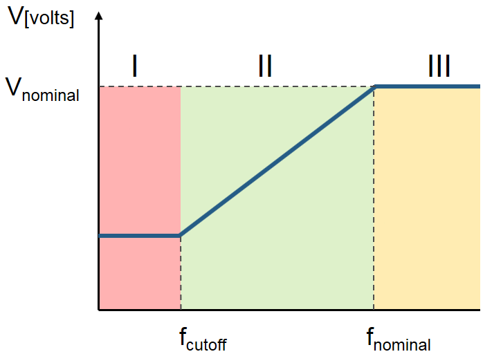
Figure 1 The V/F scalar control is the most common control strategy used for induction motor drives. In case of PMSM, the V/F scalar control is a good alternative in applications where good dynamic performance is not required (e.g.: HVAC, fans, pumps or blowers). In such cases the V/F scalar control is performed without the need of a position/speed sensor.
In case of PMSM, both open and closed-loop control of the speed can be implemented based on the V/F scalar control. Open-loop control is used in applications where system dynamic response is not a concern. For such use cases, the frequency is determined based on the desired speed and the assumption that the rotor will ultimately follow the synchronous speed.
Throughout this module we are going to implement an open-loop control system topology for a 3-phase PMSM using V/F scalar control as the one shown in Fig. 2. Such control structure will allow us to control the PMSM speed without any feedback of motor parameters or rotor position. The motor is driven by the conventional 3 phase voltage-source inverter via MotorGD DevKit.
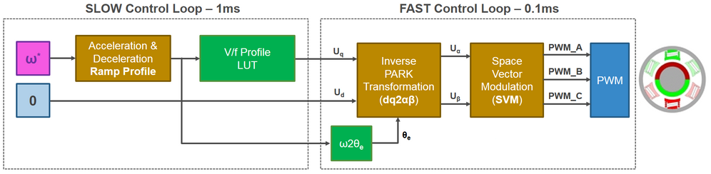
Figure 2, V/F scalar control block diagram In order to maintain a similar topology with two control loops and similar data structures for the examples that we are going to use in this workshop, we are going to implement the V/F scalar control application based on:
- FAST control loop is executed at each 0.1ms and computes the PWM duty cycles based on Space Vector Modulation. The reference voltages for (dq)-axes and the motor electrical speed represent the inputs. The electrical angle needed for Inverse Park Transformation is computed based on electrical speed reference.
- SLOW control loop is executed at each 1ms and provides the voltage references for Inverse Park transformation and the electrical speed profile. Inside this loop, the user commands are handled and based on a parameterisable Ramp Profile the appropriate control parameters are generated. The V/F profile is implemented via a tunable Look-Up-Table (LUT)
Source: https://community.nxp.com/t5/Model-Based-Design-Toolbox-MBDT/Module-5-V-F-Scalar-Control/m-p/726087
반응형'Motor Control > BLDC 모터 제어' 카테고리의 다른 글
Timer1 for motor control (20kHz) (0) 2025.12.02 Uart DMA (0) 2025.12.02 Hardware setup for BLDC FOC control with AS5600 (0) 2025.12.02 위치 센서 (AS5600) (0) 2025.12.01